Update I
- fsae-mmi

- Nov 1, 2019
- 5 min read
Our group is working on the braking system for the University of Houston’s Formula Society of Automotive Engineers team (UH FSAE). The UH FSAE team is a student organization that builds a formula style race car each year and competes in a nationwide competition. The organization is broken up into five different teams that are responsible for different components of the car. Our team is the Man-Machine Interface team (or MMI) and we are responsible for the braking system of the car.
Over the past few years, the braking system has performed poorly due to a low pedal ratio, incorrect bias bar, late fabrication and a heavy pedal box. If our team can successfully build a working braking system, this year’s car will be able to pass the FSAE Brake Test at competition, a feet that has not been accomplished ever since 2016.
Recently, from Oct. 18 - Nov. 1, our team has decided on a preliminary pedal box design. The pedal box design is essential for the braking system because it is the only way the driver can use the brakes. We looked at the pedal box from the 2016 car which is in Engineering Bldg 1. It was helpful to see an actual pedal box in person and see how it was attached to the chassis. Our attachment of the pedal box will be derived from the 2016 car because of its stability and how easily it can be mounted. The mount for the master cylinders was also designed with stability in mind. Also, a few adjustments to the pedals are being made in order to fit the weld on pivot bushings from a potential manufacturer. Lastly, our team uploaded our CAD drawings for the rotors, calipers, and pedal box onto OnShape to see the compatibility with the chassis and wheels.
Even though we made progress, the project had its challenges. One of the ongoing difficulties for a few of the members is learning how to use the online CAD program, OnShape. We are working together to learn the software and are watching tutorials when we get stuck. Another challenge that we are still working on is the mounting of the pedal box. We had an initial mounting design, but it seemed bulky and heavy so we wanted to find a way to remove material from the base. With this in mind, we came up with a design that did not have as much material, but is still stable.
Project Progress from the Beginning
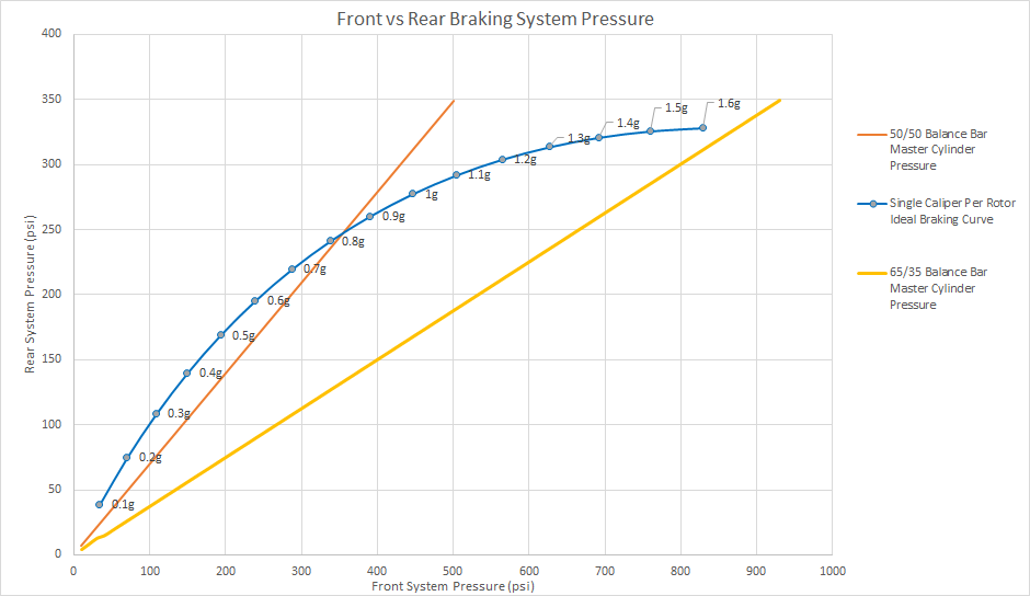
Ideal Braking Curve for 45/55 Axle Weight Distribution (Front/Rear)
The foundation of the braking system is the ideal braking curve, which plots the front braking system pressure against the rear system pressure for the case when the tires don’t slip. The ideal braking curve is nonlinear because the braking forces in the front system increase while the forces in the rear system decrease due to weight transfer. As the deceleration of the car increases, the amount of weight on the front axle increases due to momentum transfer as a result of the vehicle’s center of gravity height with respect to the wheel base. Above and below the ideal braking curve are regions where the tires begin to lock-up and slip. The region above the ideal curve is where the rear tires being to lock up and slip, while the region below the ideal curve is where the front tires begin to lock up and slip. The 50/50 Balance Bar line is the increase in the front system vs. rear system pressure for a given force input to the push rod to each system’s master cylinder. The 65/35 line represents the maximum biasing that the balance bar we are using will allow. Our goal is to balance the front and rear brakes such that the pressure line for the master cylinder input intersects the ideal braking curve close to 1.6g, which is the deceleration when traction between the tires and the road is lost. During braking, loss of traction in the front tires is preferable to loss of traction in the rear tires for the purpose of vehicle stability.
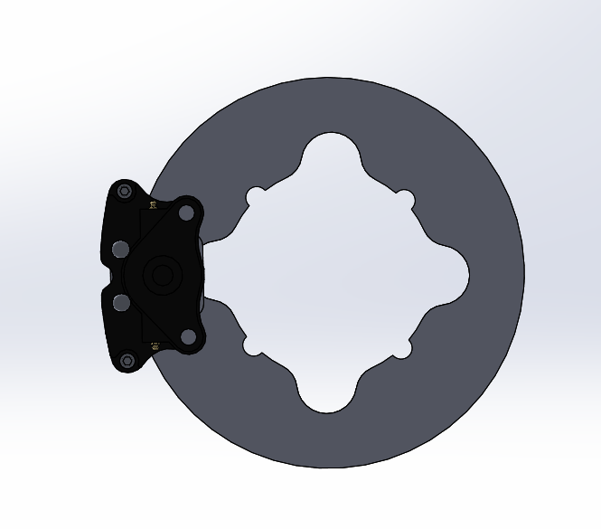
Brake Rotor and GP200 Caliper
The rotor we intend to use on the 2020 FSAE car is a 7.5” diameter, 0.187” thick, and made from Dura Bar G2 Cast Iron. The rotor material selected for this year’s car come from cast iron blacks sold by Kaz Technologies for FSAE teams to fabricate brake rotors from. The company has supplied our team these blanks for the past two years and they have performed sufficiently. In the interest of focusing our time on other components in the pedal box and braking system, we’re planning on sticking with a similar rotor design to the previous year teams. The rotor is fit onto a rotor-hat attached to the wheel hub. Rotor pins fitted with circlips will allow the rotor some freedom to float until it is clamped onto by the caliper. The rotor pins will restrict the motion of the rotor enough to keep it attached to the rotor-hat and prevent unwanted rotation, while allowing enough free play to prevent unwanted bending stress in the rotor.

Preliminary Top-Down Mounting Geometry for the Pedal Box
The current method of mounting the pedal box being considered is comprised of solid support bars going across the chassis. Perpendicular to the support bars will be two rails which the base-plate of the pedal box will attach to. The trapezoid in Plane 1 is the space available to us to mount the pedal box.

Most Recent Pedal Box Iteration
An overlay view of the pedal box assembly on the preliminary mounting geometry is provided. It is important to note that the pedal box will not have freedom to move all the way to the base of the trapezoid, due to the geometry of the driver model we are using. Future changes in the mounting geometry will likely include a reduction in rail length and the number of cross-bars. The Base-Plate of the pedal box will likely be split into two pieces to reduce material. Our design aims to provide the driver with a pedal ratio of 6:1 and the ability to bias the braking system to 65/35. Space at the rear of the pedals were provided to allow for adjustment of the pedal positions, specifically the brake pedal with respect to the master cylinders.
For the work period from November 1 to November 15 the MMI team plans to finalize the designs for the pedal box and input the assembly into OnShape to verify compatibility with the chassis and other teams components. Once the design is finalized, a complete parts list can be compiled, any recycled parts from previous years can be collected, and an updated budget can be calculated. The only challenges we anticipate would be the pedal box design not fitting into the chassis design in OnShape or not having proper placement of components with other team’s designs.


Comments